You will need to do a little customizing of the source code that HIDmaker FS generates, but hey, we had to leave you something to do, right?
Customizing the PIC Code
To keep the generated PIC code as flexible as possible, HIDmaker FS generated PIC code does no hardware dependent I/O other than USB. You see, HIDmaker can't know what I/O pins you'll want to use, what A/D channels you'll use (if any), or what other PIC peripherals you'll need to use in the PIC software in your HIDmaker USB peripheral device.
Adding "real I/O" in your PIC code is YOUR job. Many of our customers find that our generated code is so complete, they only need to add about a dozen lines of PIC code to make a pretty good USB device. (Of course, your job may be more complicated, but that's OK, we're here to help!)
Even if you have to add some more complicated PIC code to your generated firmware, you will find that the PIC side code of the HIDmaker Software Framework is designed from the ground up to be powerful, yet easy to understand and extend. And for you, as a registered HIDmaker FS customer, expert help and advice is always just an email or phone call away.
Customizing the PC Code
HIDmaker FS does generate a complete, CUSTOM, ready to compile and run Windows Graphical User Interface (GUI) program for you: a program that is match to the PIC device code which was generated as part of the same project. However, in order to be able to do that with all the different PC compilers we have to support, HIDmaker generates a functional, but bland looking user interface:
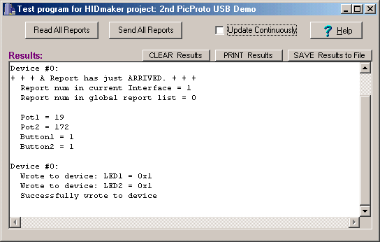
We expect that you will probably want to dress up the appearance of your PC program, and give it a user interface that makes sense for your particular application. It is very easy to do that with most of the modern PC compilers that HIDmaker FS supports.
As an example, here is how we were able to transform a demo program that runs on our favorite USB test board, the microEngineering Labs LABX-USB board. This demo board contains the following I/O controls:
- A 2-line LCD display
- A 4 x 4 array of pushbuttons
- 4 LEDs
- 2 pots
By deleting the big text box on the main window, and adding a few colorful third party controls, we were able to transform the functional but bland looking main window of the generated code into something that looks much better:
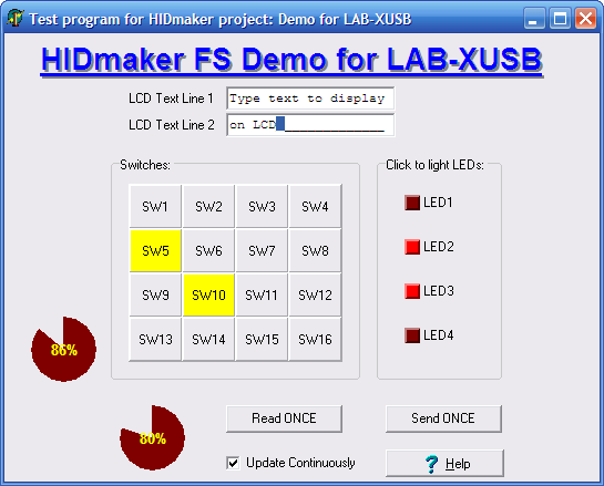
This took about an hour’s work with Delphi.
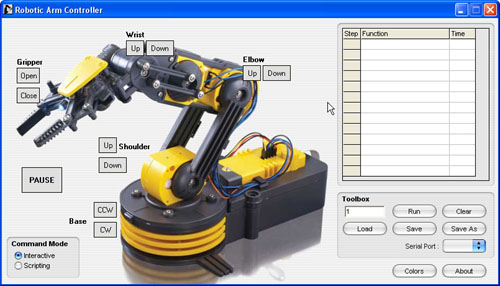
HIDmaker is designed to make it easy for you to modify and beautify your PC program, to give it the look and feel that you've always dreamed of. Depending on what hardware your HIDmaker has to control, you might add a picture of it to dress up your program like John Iovine of Images Scientific Instruments did. (You can learn more at this page in our Customer Showcase section.)
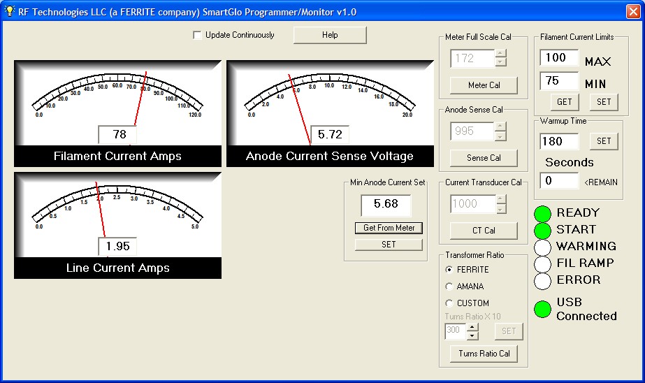
Or if you are monitoring something, you might want to add some attractive gauge controls, like David Lawson of RF Technologies LLC did. (Check out his page in our Customer Showcase section.)
By the way, we'd LOVE to show off YOUR work in our Customer Showcase section as well. If you're interested, contact Dr. Bob and let's talk!
Recommended USB Development Procedure
We recommend that you follow this procedure after you generate your code with HIDmaker FS :
- Use a known-good commercial USB demo board the first time you test a HIDmaker FS project. We guarantee HIDmaker's code to work, but we cannot guarantee that your new PC board design works right away. If you try a software tool like HIDmaker FS for the first time, on a board design that may or may not work, you'll have too many uncertainties to debug.
- Get your peripheral device running first, exactly as it was generated by HIDmaker FS. (If you want, you can just use the AnyHID test program, part of HIDmaker FS , to test your PIC code without even having to compile the generated PC code.)
- Next, be sure to compile HIDmaker's PC program, exactly as it was generated by HIDmaker FS , so you have a PC program that is specifically matched to your PIC device.
- Now, add at least a little "real I/O" code to your PIC, so you can see something change on each side when you send data. For instance, if there is an LED on your board that can be lit from your PIC device, it's a good idea to add code to turn that LED on or off, depending the value of a data item that is sent from the PC. Similarly, if there is a pushbutton or a pot on your board that can be read by the PIC processor, be sure to add some code to actually read that button or pot, and change the value of one of the Input data items accordingly. You know that your communication is working if you can change something on one side (PC or peripheral), and see some visible change on the other side that you expect.
- Modify your PC program a little at this point, so you can easily change the data values that the PC program sends to your PIC. You can do this by adding some sliders or buttons or check boxes to the main window of your PC program. Use these controls to change the values of the variables that your PIC code uses to turn an LED on or off, and you will be sure that your USB communication is working correctly.
- Now that you are sure that your USB communications are working correctly in both directions, you can continue to modify both your PC program and your peripheral firmware, to move in a step by step fashion toward the final goal you envision. We recommend that you change only one thing at a time and test that one change. That way, if anything goes wrong, you always know where the problem is: always in the last thing you changed.
To learn even more strategies for customizing both your PIC code and your PC code, download our free guide to the tips, techniques, strategies, and mind set that will turbo charge your USB development!
Next: Requirements >>
Quickly make CUSTOM, ready to compile and run USB HID class source code written for YOUR FAVORITE COMPILERS, MATCHED for both PC and PIC device at the same time, that sends data that YOU defined.
Now you can also get an "unfair advantage" over your competitors, with 16-bit and 32-bit USB PIC devices, as well as 8-bit USB PICs, with new HIDmaker 32. Gets your USB HID project running, and communicating YOUR custom data, in as little as 10 minutes! Pays for itself in 1 day !
NEW! 2 Versions -- See which one is right for YOU :
Learn about new HIDmaker 32 for 32-bit, 16-bit, and 8-bit USB Processors
Learn about new Enhanced HIDmakerFS 2 for 8-bit USB PIC Processors