Page 1
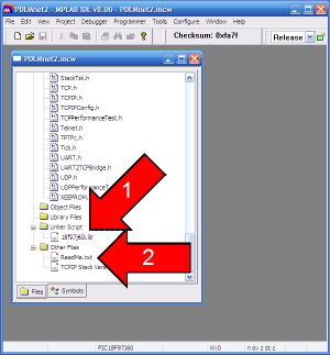
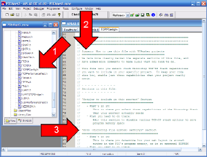
Before we do anything, let's use Windows Explorer to look at the directory tree that TCPmaker generated in the new project directory we created for our project.
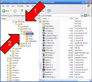
Arrow 1 shows that we named our project directory PDN2Copy. Underneath that is a directory called PIC, and under that, there are 4 subdirectory trees, one for each of 4 compilers that we generated code for.
Arrow 2 shows that we are currently interested in the MCHP_C18 directory tree, which holds the code that was generated for Microchip's C18 compiler. (We are interested in running our project on a Microchip PICDEM.net2 demo board.)
In this directory tree, the Microchip directory contains all the files for the Microchip TCP-IP Stack. We won't need to modify those.
The directory we have highlighted and pointed at with arrow 2 is the TCPmaker subdirectory. This contains the generated code, the instruction file ReadMe.txt, and the MPLAB project file.
Click on the image for page view.
Page 2
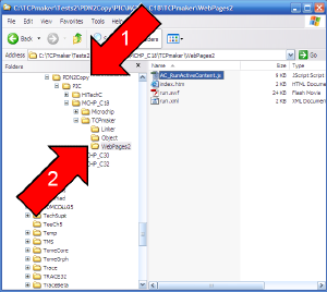
The subdirectory WebPages2 contains the Web content that our TCPmaker embedded web server will send to the PC browser:
index.htm contains a small HTML page that serves as a container for our Flash based TCPmaker layout.
run.swf is a very smart, but very small, object oriented class library that knows how to create and position any number of the Controls (like buttons, indicators, sliders, and so on) that the Visual Page Designer let us create.
run.xml is a set of instructions that tell run.swf where to put the controls we want, what color they should be, and so on.
AC_RunActiveContent.js is a small Javascript file that allows our layout to run right away, as soon as it is displayed, rather than waiting for the user to click the layout first.
Click on the image for page view.
Page 3
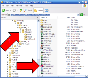
As instructed in our last tutorial, we printed out ReadMe.txt, and are now following its instructions. We go back to the PDN2Copy\PIC\MCHP_C18\TCPmaker\ directory, and open the MPLAB project file, which in this case is called PDEMnet2.mcp.
(We can just double-click this file in Windows Explorer to open the project in MPLAB.
Click on the image for page view.
Page 4
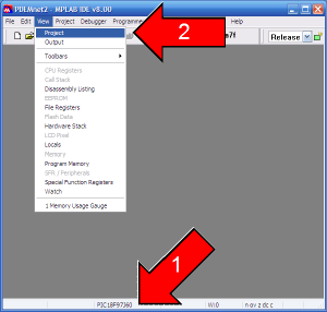
Follow the instructions in Readme.txt to set the processor type we want (PIC18F97J60 in this case, and click menu item View | Project to display the project file tree window.
Click on the image for page view.
Page 5
Luckily, our C18 project settings as created by TCPmaker default to the processor and linker script we want.
Let's double click ReadMe.txt, in the Other Files section, so we can keep our checklist handy on screen.
Click on the image for page view.
Page 6
As per instructions, we need to locate the file HardwareProfile.h in the Project window and double click it to open this file, so we can set the hardware resources that should be compiled with our project.
Click on the image for page view.
Page 7
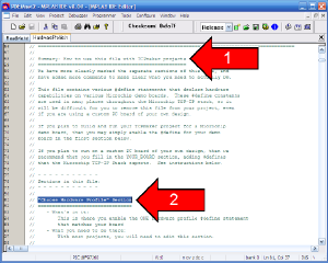
We have added comment blocks to this file to make it easier to find just what you need, and we have also added a sort of "table of contents" close to the top of the file. (See arrow 1 in the picture below.)
In this project, since it will run on a standard Microchip demo board, our job is easy. All we will need to do is locate the "Choose Hardware Profile" Section in this file and make sure that the #define statement for the right Microchip demo board has been enabled.
Click on the image for page view.
Page 8
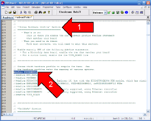
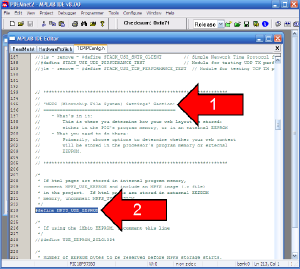
Using our Section headers makes finding the "Choose Hardware Profile" Section (arrow 1) a snap.
All we need to do for this project is to make sure that the statement
#define PICDEMNET2
is the only line that is enabled in this section.
If you plan to run your project on a different Microchip demo board, or on a custom board of your own choosing, then you will have a bit more work to do. Follow the instructions in ReadMe.txt and in the comments we have added to HardwareProfile.h, to make sure that you have defined all the constants that the Microchip TCP-IP Stack expects you to define for your hardware.
Click on the image for page view.
Page 9
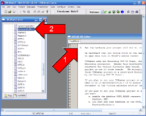
Back in the Project window, locate header file TCPIPConfig.h (see arrow 1 in the picture below) to open this file in a page of the editor window.
Close to the top of this file, you will see that we have added a "table of contents" comment block (arrow 2) to this file as well.
As the instructions in file ReadMe.txt indicate, a sure thing that we will need to check in this file is how we want our Web content to be stored in our device: should it be in program memory or external EEPROM (which may not be available on your board).
For this, our table of contents shows that we will need to find the "MPFS (Microchip File System) Settings" Section (see arrow 3).
Click on the image for page view.
Page 10
We scroll down through the file, or search with Edit | Find, until we find the "MPFS (Microchip File System) Settings" Section in this file.
For this project, we decide to store our TCPmaker Web content in serial EEPROM that the PICDEM.net2 board has. To make sure that happens, we enable the statement
#define MPFS_USE_EEPROM
in this section.
For simplicity in this tutorial, we leave the other settings in this section at their default values, including NOT requiring authentication when we upload new Web content to our device.
If this were a real production device that we would connect to the Internet, we would certainly want to change the settings to require authorization before allowing new Web content to be uploaded into the device, to protect our product from hackers.
Click on the image for page view.
Page 11
The only other thing in our checklist is to verify that our compiler search paths are set correctly. (Consult you compiler documentation for information.)
Since our compiler is set up right, we're ready to do a build of TCPmaker's generated code.
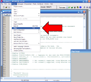
Notice that we haven't added any code to read any buttons or ADC channels or light any LEDs yet, so we're going to see what happens when we try to run the code exactly as TCPmaker had generated it.
Since the Microchip TCP-IP Stack is pretty large, we recommend that you compile your project with the menu item Project | Make. The first time you build your project, it will have to compile every module, but every subsequent build will only compile those modules that you have edited, saving you a lot of time.
Click on the image for page view.
Page 12
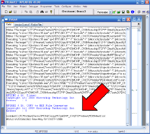
If you have followed instructions up to this point, you should find that your project, exactly as it was generated by TCPmaker, will build correctly without errors.
Now we need to program the code into our device. For this project, we'll use an ICD2 as a programmer. We won't bore you with the details of how to use this very common PIC programming and debugging tool.
In our next page, we will show you what happens when we connect our device to our network, run our device and point our PC browser at it.
Click on the image for page view.
Page 13
Since we set up our project to store our Web content in serial EEPROM on the PICDEM.net2 board, we need to perform an extra step of uploading the content to our board.
The settings we chose in TCPIPConfig.h will allow us to do that over http in our browser.
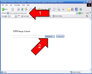
Step 1: Point our browser to our board. We use the NetBIOS name for our board, as described in the Microchip TCP-IP Stack documentation, so we point our browser to this address (arrow 1):
http://mchpboard/mpfsupload
This will show the web form in the picture below.
Step 2: Click the Browse... button on the form to find our content. (Arrow 2)
Click on the image for page view.
Page 14
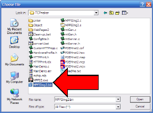
In the Choose File dialog that comes up, we navigate to the same directory that holds the MPLAB project file, and we select file MPFSImg2.bin in that directory.
Then click the Open button on the dialog.
Click on the image for page view.
Page 15
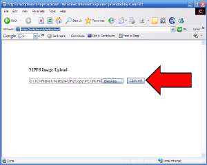
Now click the Upload button on the form in our browser, to actually upload our Web content and store it in serial EEPROM on our board.
Click on the image for page view.
Page 16
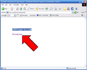
When this process finishes, you should see the simple "MPFS Update Successful" page shown below.
Click the "Site main page" link to go to the index page of your TCPmaker content.
Click on the image for page view.
Page 17
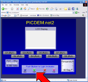
This will display the index page of your TCPmaker layout, with all the background colors and controls that are present on that page.
The gauges don't display any values, because you need to add some code to send the data to the PC.
If you click one of the pushbuttons, you will see its appearance change on the browser when it is in the "down" or "active" state, but since we haven't added any code of our own to what TCPmaker generated, the PIC device simply ignores any data sent to it.
There is one thing on our page that is changing, though: the green circular indicator light labeled "RB1" (see red arrow) is flashing about once a second, to let us know that our TCPmaker device has established a live connection that is actually able to send data.
In our next tutorial, we'll explain the special "blink" code that does that, as we also take a tour through the generated code, and learn how to add our own code to customize it and to add "real I/O" to our device.
Click on the image for page view.
|